Tube preamp modification for Bush Acoustics AMP2025
Written on August 22nd , 2022 by Georgi Kiselov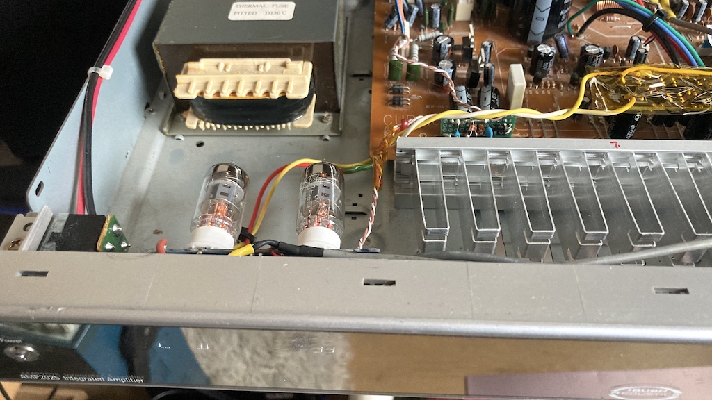
Overview
Hello Dear Reader,
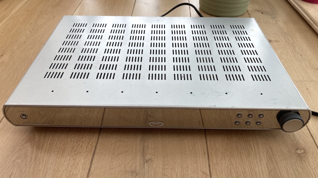
Recently I was browsing eBay to find an interesting case for my new tube power amplifier. For experiments and tests I have been using old equipment to case my projects. In this way I am reusing old equipment and save The Planet from electronic waste. I bought a Bush Acoustics AMP2025 amplifier. It has a low profile case with a lot of holes on top and bottom, which means it has a very good ventilation. Price was around £65 without postage. The plan I had in mind is to remove all internals and host my own tube amplifier and use this lovely ventilated case and rest of the parts for other builds.
When it comes home, I opened it and I was surprised how good it was build! It have very clean design and all areas of the board are marked like: “Preamp, Power, Protect, Phono EQ, Input part…” etc. The left and right channel are marked and separate on the board. Audio signal comes from two twisted cables from the preamp to the power amp to each channel.
Expired from Lampizator website I decide that this little amp is a perfect candidate to integrate a tube preamp.
6J1 Preamp board kit
For the preamp I used 6J1 preamp kit bought from AliExpress.

or this one.
Preamp comes with all parts and schematic you can see on the website. Some variations of this kit comes with 470uF 35V electrolytic capacitors, others with 470uF 50V. This is important for my build, because I am using the power from the amp it’s self to power the preamp. The amp works on center tapped +37.5V -37.5V and capacitors on 35V will not fit in this case.
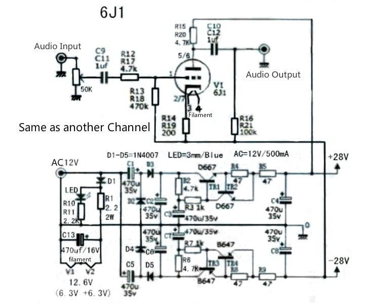
Original schematic:
The amplifier board
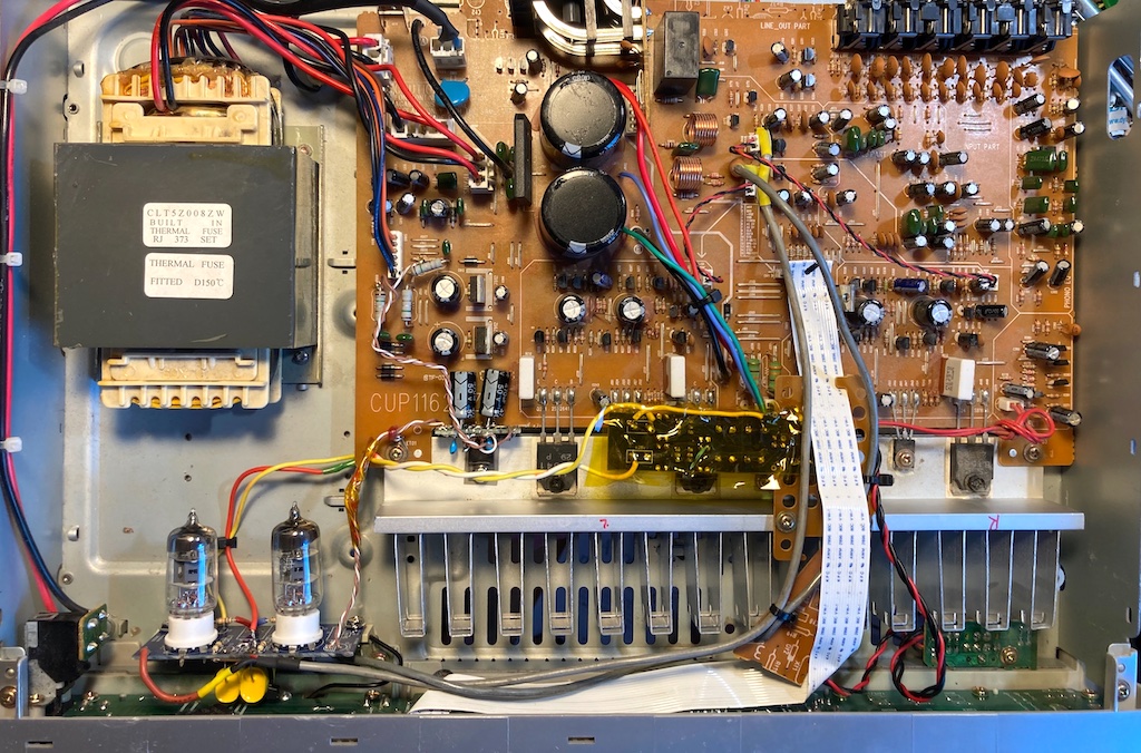
Let’s have a look on the amplifier board.
I did try to find Service manual for Bush Acoustics AMP2025 without success. So, I had to reverse engineering how this amp was build and what were the ideas of Bush engineers, when they designed the amp.
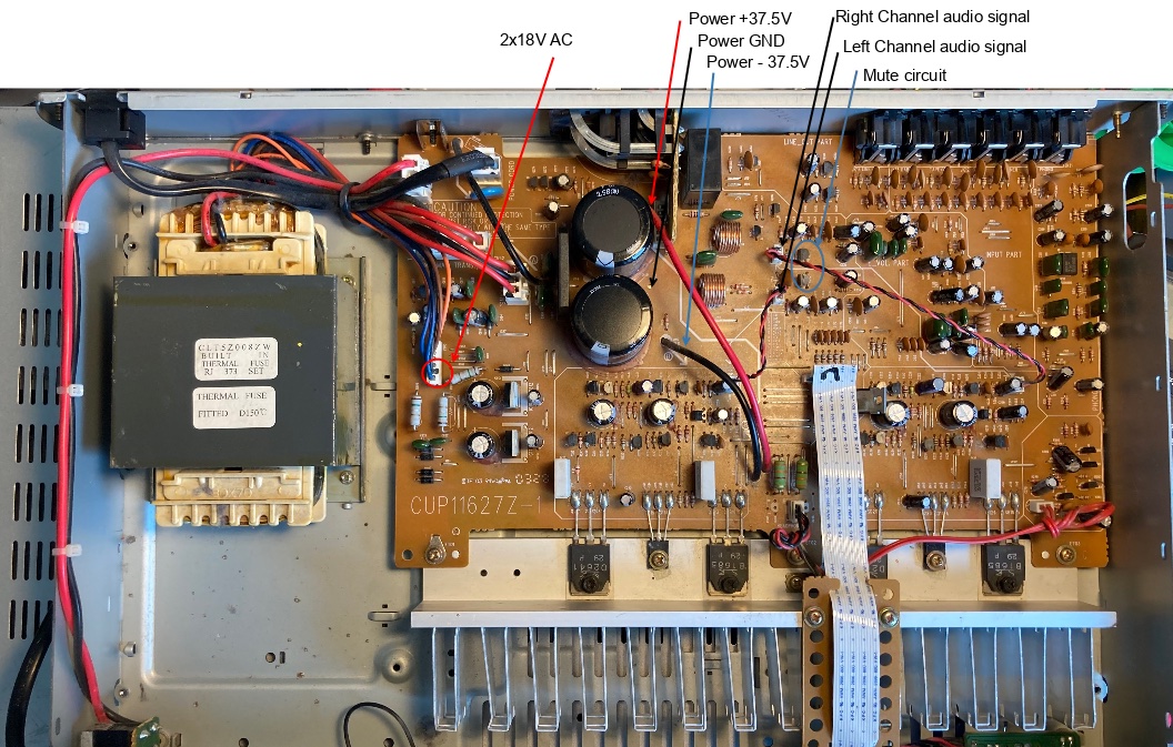
It is very well designed amp, indeed! As you can see on the picture, L and R channels of the power amp are well separated and there is a twisted pair cables, connecting inputs of the amp to the outputs of the preamp. There is a Phono preamp as well (on the right of the picture), which is a very good for vinyl lovers. It uses JRC2068 Low Noise Dual Operational Amplifier. There is 5 inputs, including Phono and one line out output. Next to speaker connectors, you can see the relay. It has about 6 sec. delay, when amp is powered up. Huge filtering caps 6800uF/50V each. Input selector, volume, balance, tone, etc. are microprocessor controlled via the white cable in the middle. Front panel has a very nice display, volume wheel and knobs.
When I saw this layout, I thought “Fantastic! I will cut R and L twisted pairs and connect the tube preamp there.” And I did it… :)
The result wasn’t very good.
- There was a hum on both channels.
- When turn the amplifier on, the speaker relay have around 6 sec. delay, and this is not enough for tubes to warm up. In result there was a strange noise on speakers until tubes warms up. They requires around 9-10 sec. to start working properly. At this time I was using the 37.5V DC directly from the amp, avoiding building the filtering circuit on the tube preamp. (lazy chap)
- There ware a clicking noise, when I switched the inputs, using buttons on the front panel.
Let’s tackle the problems one by one.
Heater power supply
There is various reasons to have a hum in tube amplifiers. One is from heaters when using AC power, another could come from ground loop. To eliminate the hum from heaters, I decided to build DC 12.6V power for heater. Tube 6J1 has 6.3V heater and two tubes in series equals 12.6V. For that purpose I used 7812 voltage regulator. Schematic is standard with additional diode on GND connection to lift the voltage from 12V to 12.6V.
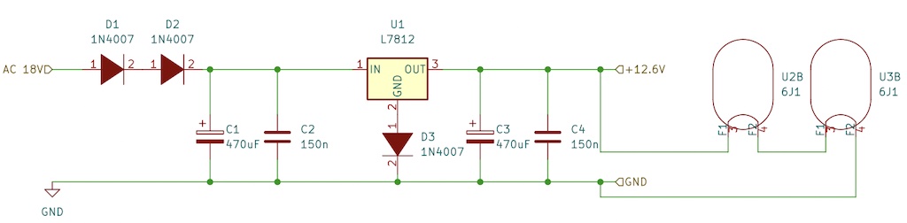
Schematic was build on piece of prototyping board and parts was reused from other electronic equipment. This resolved the hum problem caused by heaters. AC power I took from resistor R909 on the board and GND from J202.
Power supply with delay
Tubes requires some time to heat to start working properly. For 6J1 tubes I measured around 10 sec. The original schematic (Fig. 3) has time delay and filtering on + rail and - rail. Left part of schematic has voltage multiplier, which I am not using, because the amp already has positive and negative rails with 37.5V. So, I build only from C2 and C6 right, ignoring left part. From C3 and C7 depends the delay time. With this schematic I achieved around 10 sec. delay till full power. With this part I resolved the second problem from the list above. In this way there is no scratching sound on speakers, when I turn the power amp on. The source power for this board comes from marked on Fig. 4 Power +37.5V, GND and -37.5V.
Audio input / output / ground
Initially I connected the preamp directly between build in preamp (OP) and power amplifier by removing twisted pair cables and used one end as a input to tube preamp and the other end was connected to tube preamp output. Everything was working as expected with a little exception… there was a clicking sound, when I switched amp inputs from front panel buttons. After I spend some time armed with magnifying glass, I notice that the amp has a mute circuit, just on output of the build in preamp (OP). I marked this area on Fig. 4 as “Mute circuit”. Then released that I do not need to cut the twisted pair bridges between preamp and power amp parts of the board. I can just include the tube preamp between the OP preamp and mute circuit. In this way the mute circuit actually will mute the power amp, when I switch between inputs from the front panel. The input/output signal I took from resistor R339 and R340 near the area marked as Mute circuit on Fig. 4 and signal ground I took from one of the legs of C165, near the preamp L output. In this way I resolved problem 3 and part of 1 (ground loop) from the list above.
Tube Preamp schematic
Original schematic (Fig. 3) actually invert the signal. I wanted not inverted signal or tube cathode follower. I found a discussion on diyAudio, from where Mona purposed next schematic.
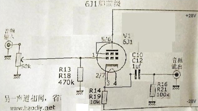
This simple schematic can fit on preamp board very nicely without much of a changes. I am not using input potentiometer. Preamp is directly connected to the output of the OP on the main board.
Board modifications
The AMP2025 is a low profile. I wanted the tubes to be horizontal, but the preamp board was too big. Here is how I cut the board in order to fit it inside the amplifier.
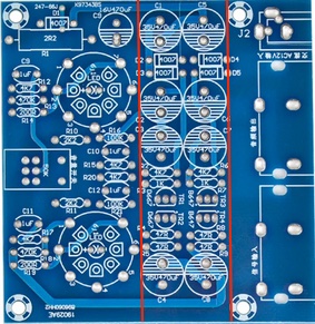
Left part I used to build Tube PreAmp Cathode Follower. Middle one to build Time Delay Power Supply and the right I am going to use in some other project.
Here is the final (or semifinal) build.
How is it sounds?
It sounds very, very nice for my ears. Very good and strong base and relaxing music spectrum.
Final thoughts
This was a very much of a experiment. All parts, I used, comes with the preamp kit, others I reused from electronic boards laying around. I bet this preamp will sound even better if I used expensive capacitors and special resistors. But this wasn’t the purpose of this build.
Have Fun!
Georgi